
The Anatomy of a QR Code
A QR code looks like noise. It is not. Roughly a fifth of every symbol is fixed machinery that never changes, and knowing which fifth tells you exactly where a code is fragile and where it is not.
The map
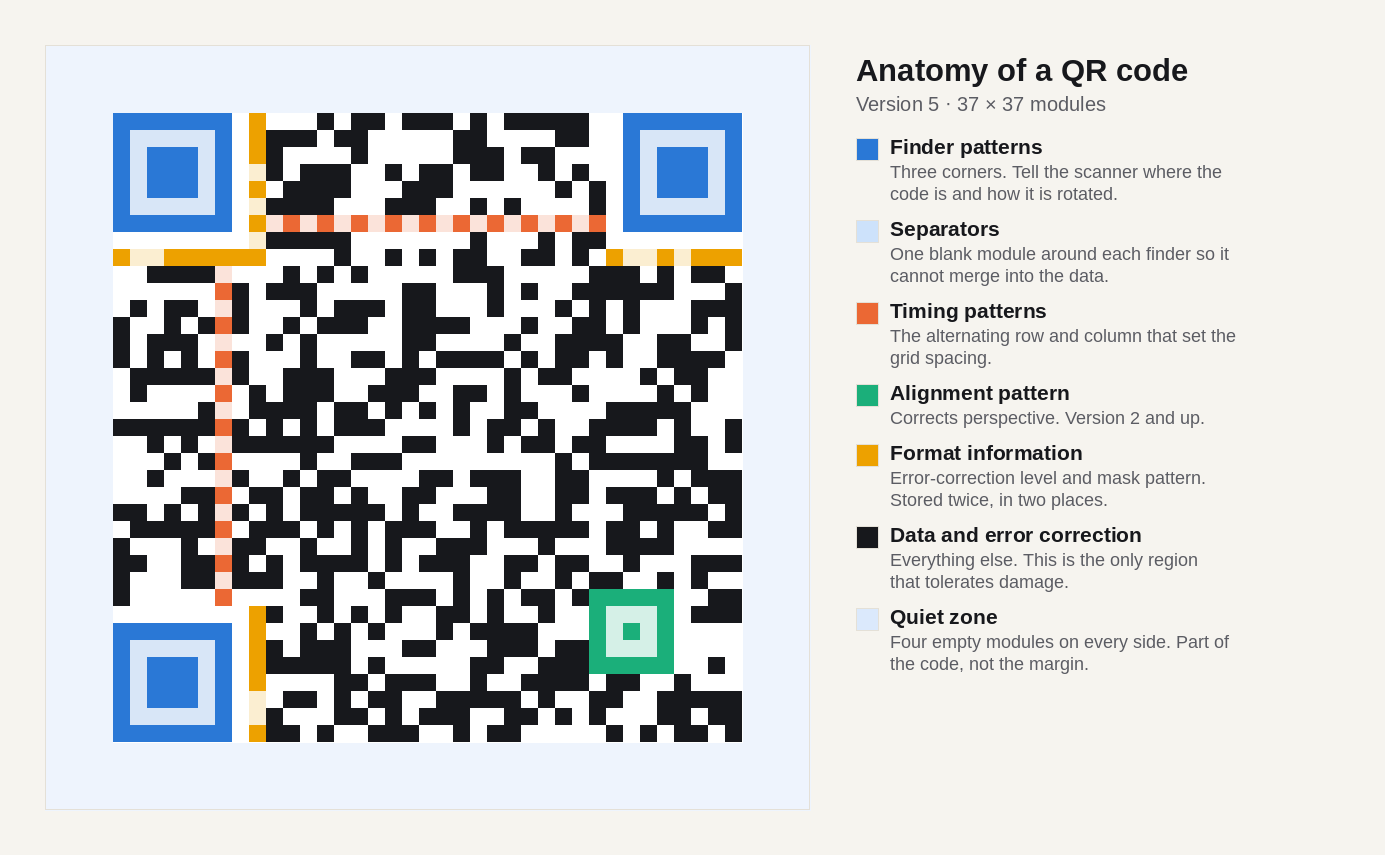
Count it up and the fixed machinery in this symbol occupies 290 of 1,369 modules — 21% of the code before a single byte of your link is written. On a version 1 code the overhead is proportionally much worse; on a version 40 it almost disappears. That is one reason very small codes hold so little.
The three big squares
The three concentric squares in the corners are finder patterns. They exist so a scanner can locate a code in a camera frame full of other things, at any angle, without being told where to look.
Their design is not arbitrary. Scanned along any line through the centre, a finder produces a run of dark and light in the ratio 1:1:3:1:1 — a signature that is rare in ordinary images and, usefully, unchanged by rotation. A decoder sweeps rows and columns hunting for that ratio, finds three of them, and now knows the code's position, its size and its orientation: three corners define the fourth.
Each finder is wrapped in a one-module separator, a blank ring that keeps the pattern from merging into neighbouring data and destroying the ratio.
Because everything downstream depends on them, finders have no redundancy at all. In our own testing, obscuring a single module of one finder made the symbol unreadable at every error-correction level — see the measurements. If a design crops, rounds or overlaps the corners of a QR code, the design is broken, regardless of how much of the rest survives.
The fourth, smaller square
From version 2 onward there is at least one alignment pattern: a smaller 5×5 square, usually near the bottom-right. Three finders tell a decoder where the code is; the alignment patterns tell it how the grid has been distorted.
A code photographed at an angle, or wrapped around a bottle, or printed on a curved lid, is no longer a square grid in the image. The alignment patterns are known landmarks in the middle of the field, so the decoder can fit a warp rather than assuming a flat rectangle. Bigger versions carry more of them — a version 40 symbol has 46.
This is why a large code on a curved surface often reads when a small one does not: the large one has interior landmarks to correct with.
The dotted lines
Running between the finders, along row 6 and column 6, is the timing pattern: a strict alternation of dark and light modules. It is the ruler. Having located the corners, the decoder still needs to know exactly how wide one module is, and small errors accumulate across 37 or 177 modules until the sampling grid drifts off by half a cell. The timing pattern re-synchronises it.
Like the finders, it is unprotected. One module lost from the timing row broke every code we tested.
The stripe nobody notices
Format information is a 15-bit block sitting alongside the finders — the L-shaped strip beside the top-left square, repeated in two segments near the other two. It records two things: the error-correction level, and which of eight mask patterns was applied.
Since nothing can be read until this block is read, it is stored twice, in two physically separate places, and protected by its own BCH code. It is the one part of a QR code with belt and braces.
Versions 7 and above add a similar version information block, so a decoder does not have to infer the symbol's size from its pixel dimensions.
The empty margin is part of the code
The specification requires four empty modules of quiet zone on all four sides. This is not padding for aesthetics. Edge detection needs somewhere to see the code stop; without it, a dark background merges into the outer modules and the finder ratio never appears.
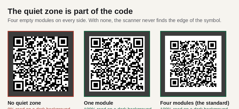
The honest result from our test bench: the decoder managed with a single module of margin on a flat dark background, and failed completely with none. Do not design to that floor. A photograph, a patterned tablecloth or a printing misregistration eats margin quickly, and four modules is the number every scanner is built to expect.
Why the same data draws a different picture
Encode the same URL twice and you may get two different-looking codes. That is masking. Raw encoded data often produces large blank patches or accidental stripes that look like a finder pattern, and both confuse decoders. So the encoder XORs the data region against each of eight fixed patterns, scores the results with penalty rules — long runs of one colour, 2×2 blocks, false finder ratios, an unbalanced dark/light mix — and keeps the best one. The choice is recorded in the format information so the decoder can undo it.
It is worth knowing because it explains an otherwise unsettling observation: two codes that carry exactly the same link, generated seconds apart by different tools, can look nothing alike and both be correct.
Versions, and why codes get denser
The grid size is the version: 1 is 21×21, and each step adds four modules per side up to 40 at 177×177. A generator picks the smallest version that fits your data at your chosen error-correction level.
| Version | Modules | Bytes at L | Bytes at M | Bytes at H |
|---|---|---|---|---|
| 1 | 21 × 21 | 17 | 14 | 7 |
| 3 | 29 × 29 | 53 | 42 | 24 |
| 5 | 37 × 37 | 106 | 84 | 44 |
| 10 | 57 × 57 | 271 | 213 | 119 |
| 40 | 177 × 177 | 2,953 | 2,331 | 1,273 |
Every extra version means more modules in the same printed square, so each module gets smaller and the code needs either more physical width or a closer camera. This is the whole argument for keeping the payload short — covered in how small a QR code can be and in how much data fits in a QR code.
Written by Manuel Llovet, who builds and maintains QR Code Free Forever. Published 2026-08-31, last checked 2026-09-08. Figures and measurements on this page were produced for this site; the method is described in each caption.